So, faulty encoder desoldered. It was a huge pain in the ass.
Disassembling the unit is actually very easy. Desoldering the encoder is very tedious.
Tools disassembly:
- Screwdriver to remove the boards.
- Allen key to open the chassis.
- Nut socket wrench to remove nuts on knobs without damaging the pedal surface.
- Spudger to open flat cable connectors.
- Small tweezers, preferably plastic.
- Small pliers to get out the PCB connectors.
Good to know disassembling:
- The Volume knob hat can be stuck harder than the rest. The others you can just pull by hand but you want to carefully wiggle the Volume knob out as that knob is its own separate little PCB so don't pull too hard.
- The flat cable between the two halves can be a bit tricky to get out and back in since it's right against a footswitch. Use a spudger.
- The touchscreen cables are also a bit finicky, just work carefully and slip them under the PCB they are connected on.
- Remove the processor/memory board (small board with a metal backplate).
- It's good to remove this so you have more room with your soldering iron and don't risk scorching the brains.
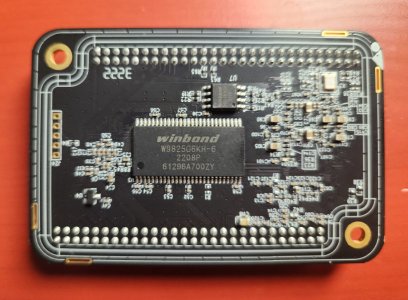
- I thought the backplate was a heatsink but it's just a cover, under it you can find a Winbond chip of 256 GB DDR3 or DDR4 I think.
Then on to actually desoldering the encoder.
Tools for desoldering:
- You absolutely need a proper soldering station! Even with one, I had a helluva time getting enough heat going to get the solder out of the larger tabs holding the encoder.
- A PCB holder is a very useful tool to help you.
- Solder wick.
- Desoldering pump.
- Good solder, duh!
- Good lighting is essential.
- A magnifying glass and a small flashlight are great for actually seeing if you got the solder out.
Good to know desoldering:
- Be very careful around a few places:
- The multi-pin connector for the "brain" PCB. I slightly scorched mine because I tilted my soldering iron a bit too much, but thankfully no real damage was done and I could get the PCB back on just fine.
- There is a surface mount resistor very close to the center encoder's 3rd leg, and there are others close to the other encoders.
- The pins of the encoder are close to the footswitch PCB jack, so avoid melting that.
- The actual encoder is held by 3 pins, and 2 legs.
- I recommend you treat the encoder as a goner because I broke one of its pins getting it out and mangled it a good bit too.
- It's best to desolder the legs first, then you can bend it out so it's hanging by the pins and desolder them. The encoder should then just drop.
- Finally clean up any stray solder, metal bits etc. I use a bit of isopropyl alcohol to clean it up with a small brush, and finally use a bit of canned air to dust it off.
Finally just assemble it back together in reverse order. It will work fine without the encoder, you can use the param/value knob as a replacement until then or operate the middle button with the touchscreen. It's great that Hotone has fallback options like these!
So what about replacement parts? I contacted Hotone, and they said then can ship me spare encoders! Will probably take a few weeks to arrive.
 R It's great.