New Pedal Day (Kit build, finally finishing up)

If this is new to you, you might find the quality of your solder joints improves over time (or gets worse as you get tired, bored and frustrated). Just keep at it and eventually you get a feel for how much solder you need to add and how long you need to hold the iron there for to get it to flow evenly around the leg and cover the hole. I sometimes give the component a little wiggle and make sure that the leg on the other side of the PCB isn't moving at all - sometimes the solder sticks to the pcb hole before it sticks to the component leg (especially if the leg's oxidised or covered in sticky residue from tape), and you can have what looks like a solder joint but that actually isn't really.

Do you have a heat sink? They're useful.
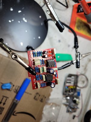
I've done plenty of soldering up till now but never on a PCB and have a couple alligator clips as heat sinks. After the first few joins I can tell that I needed to do something differently so I ended up with a bit of solder on a small corner of the iron tip, touched it to the hole, and viola. And yes I wiggled everything!
 

Attachments

  • 20230318_180224.jpg
    20230318_180224.jpg
    1.3 MB · Views: 23
I've done plenty of soldering up till now but never on a PCB and have a couple alligator clips as heat sinks. After the first few joins I can tell that I needed to do something differently so I ended up with a bit of solder on a small corner of the iron tip, touched it to the hole, and viola. And yes I wiggled everything!

Has Lee drilled the enclosure for you @Alex Kenivel?

Sorry if you know this already but it helps to mount the pots on the outside on top of the enclosure. Then you can put the pcb on the pot legs and solder them into place. Just solder the center pin from each pot and you can check they're all level, that way if you want to adjust the height of any of them you only have to reflow one solder joint. Once you're happy they're level and the same height solder the other legs and it's ready to go inside the enclosure.

You have a lot more room and much better access outside the enclosure than on the inside.
Damn I should have done that! I just soldered them on slightly crooked but fit well enough into the enclosure.

I did a dumb dumb and soldered the switch to the daughter board upside down. I'll need to pick up some desoldering wick so I'll have to stop working on this for now.

This so far has been a fun process!

20230318_194413.jpg
 
I did a dumb dumb and soldered the switch to the daughter board upside down. I'll need to pick up some desoldering wick so I'll have to stop working on this for now.


View attachment 5430

Yup been there, done that and it sucks. Depending on how much solder you put in the holes that could be an absolute pain to get off.

The pcb is looking good though. You also might want to put some tape or card on the back of the pots so the pcb doesn't ground out on them. Alpha pots used to come with plastic covers but not anymore.

Good luck and let us know how you get on. If the solder wick isn't getting the job done I can recommend this solder sucker. It's the first one I used that isn't shit, I've had mine since 2016.

Edit - I can't get the link to post. If you search Amazon for Engineer SS-02 solder sucker it's about $20 normally.
 
Yeah I wouldn't be surprised if the error rate for the switch PCB orientation is approaching 50%, I've done it too. IIRC it still works fine, you just need to run the input and ouput jack wires round to the opposite side. the switch is just alternating between connecting the middle pins to the top or bottom row so it doesn't really mind which way round it is.
 
IRC it still works fine, you just need to run the input and ouput jack wires round to the opposite side. the switch is just alternating between connecting the middle pins to the top or bottom row so it doesn't really mind which way round it is.
How? Idgi. That's outside the scope of any directions so I'm lost there
 
James is right - switches don't like heat, and I'm always very anxious about working on them with an iron more than I have to because I can imagine a situation 7 years down the line, mid gig, where that extra heating cycle causes the switch to fail when it would have gone for years longer.

Just keep following the instructions, but the two leads from the input jack will need to go round to the far side of the switch pcb to be soldered into their holes, and likewise for the two wires from the output jack. Basically, every connecting wire will still go where it's marked as going on the board, but some leads will have to be longer and the leads between the switch pcb and the main pcb will likely cross over each other since your switch pcb will be upside down.
 
Well I did some tests on the main board and all I get is the bypass sound so something's not working and I don't know what it is or how to check it :/
 
IDK what that is
How did you test the circuit?
I wired up the board to the Jacks as shown on this page:
16792667537403124620757306378587.jpg

plugged in a guitar and amp. Just getting the bypass sound and the knobs aren't doing anything.
Maybe it's my shitty newb soldering? It wasn't a graceful process. The solder I have is kinda thick. Maybe I should have thinner solder for this kind of work? I tried to desolder some of the pots but got frustrated about the whole thing in the process and begin to pound tequila. I may have fucked the PCB now...

16792669872654184614214938563585.jpg
 
IDK what that is

I wired up the board to the Jacks as shown on this page:
View attachment 5484
plugged in a guitar and amp. Just getting the bypass sound and the knobs aren't doing anything.
Maybe it's my sh*tty newb soldering? It wasn't a graceful process. The solder I have is kinda thick. Maybe I should have thinner solder for this kind of work? I tried to desolder some of the pots but got frustrated about the whole thing in the process and begin to pound tequila. I may have f****d the PCB now...

View attachment 5486
You need a solder-sucker. And don’t get discouraged. We’ve ALL been there. Luckily most quality PCB’s can take a beating. And even if the traces get damaged, they can be bypassed. 👍🏻
 
Yeah it's easy to get discouraged when it doesn't fire up first time. I'd walk away for a bit and order that solder sucker I posted earlier. You'll definitely need to reflow most of those joints. Do the backs of the pots touch any of the soldered joints on the pcb? If so the effect would be grounding itself out.

Were you getting any signal through or just silence?
 
Were you getting any signal through or just silence?
I was getting what seemed to be a bypassed signal.
I'd walk away for a bit and order that solder sucker I posted earlier.
I ordered the sucker this morning (y)

Do the backs of the pots touch any of the soldered joints on the pcb?
I cut a business card to shape and slid it between the pots and the joints.

Looking at that soldering there's no wonder it doesn't work, solder sucker and reflowing every point is needed indeed.
Newb skills confirmed. I'm also getting some thinner solder along with the solder sucker @SillyOctpuss suggested.

You need a solder-sucker. And don’t get discouraged. We’ve ALL been there. Luckily most quality PCB’s can take a beating. And even if the traces get damaged, they can be bypassed. 👍🏻
That's good to know.

Thank you all for the support and hand-holding. I know I'm in over my head but this is still overall a cool experience.
 
If you're getting some signal then you're not totally screwed. Let us know when you get the solder sucker and want to try again. Once you've reflowed your joints and reconnected that pot if it's still not working we'll talk you through troubleshooting it. We'll measure the voltages and if necessary an audio probe will tell you where the problem is.

 
Thanks, will do.

I'm also getting some finer point tips for my soldering iron. I didn't even know that was a thing but it makes sense. It'll be a while before it all gets here
 
Everything came in; solder sucker, finer point tips for the iron, and some thinner solder. Idk wtf I was thinking with the bigger solder. I didn't even think about a thinner type existing but it makes a big difference.

Not big enough because I still get no sound from the pedal...
 
Back
Top