- Messages
- 346
I hope they don't ban me... It won't happen again, playing is overrated, let's buy more gear!Wrong forum.


actually, does anybody here actually play guitar?
I hope they don't ban me... It won't happen again, playing is overrated, let's buy more gear!Wrong forum.
I mean tonally if 100W sounds "better" than 50W?there are few arguments to make them different. The phase splitter needs to drive 4 tubes instead of two, the output impdance of two tubes is ~half (you approx. double the transconductance), the output transformer, most likely, has lower resistance. Then the output votlage, for the same impedance is 1.4 times so you would need to compensate with the feedback. etc. On top of that, many 50W marshall power amps run at a relatively low voltage (the voltage that was in the datasheet btw) so the tubes are not even operating in the same point.
so yeah, there are a few arguments that points to potential differences. That doesn't mean that you couldn't design a 50W that is indistinguisable from a 100W, I guess Hi-Fi guys do this (or try to) all the time, but for a guitar amp one may want those two to be different.
") I know that there are guys that hear type of tolex of the head but realistic hearable difference:) 100W now is not needed as it was in old days where there was no stage sound systems.
I know that there are guys that hear type of tolex of the head but realistic hearable difference:) 100W now is not needed as it was in old days where there was no stage sound systems. drive.google.com
they are pretty similar but I wonder if the turns ratio is the same?. Anyway, I'd flip the coin and say that the frist one, with the 1 is the EI96I mean tonally if 100W sounds "better" than 50W?
Also have a quiz for you all. I recently wound my first output transformer in the most simple 3 sectional way on old EI102 core from I guess not top quality steel. I recorded two samples on my DIY 50W JCM800 one with bought transformer from top quality company in Poland, transformer is 5 sectional EI96 with top quality steel and second with this my. Can you guess which is which and why?
Samples where recorded as follows: Amp -> DIY reactive load from Marshall forum -> Tonex one -> DAW -> IR "LT TV MIX 7 500N" from Leon Todd free pack. Amp settings and guitar the same.
Output transformer test – Google Drive
My transformer I wound has 4k primary impedance and bought one is Marshall replacement 3.4k. Black 1 and Rock 2 is EI96:) I hear only difference in lower frequencies, where bought one sounds thinner. This test shows how little OT has influence, or my recording skills are weak, which could be true:)they are pretty similar but I wonder if the turns ratio is the same?. Anyway, I'd flip the coin and say that the frist one, with the 1 is the EI96
Ah, I was assuming that the xxx_1 and xxx_2 were the same transfomer in different playing styles... the one I guessed as EI96 has more bass, or the bass is more distorted depending how you look at it but if the impedance ratio isn't the same you can't 100% blame the interleaving or the size.My transformer I wound has 4k primary impedance and bought one is Marshall replacement 3.4k. Black 1 and Rock 2 is EI96:) I hear only difference in lower frequencies, where bought one sounds thinner. This test shows how little OT has influence, or my recording skills are weak, which could be true:)
Hello there! it's me, the stubborn JVM410h guy. (my amp saga starts on page 10 if someone if intrested :)Helllo there! It's been awhile... allmost year when I replaced all the relays, transistors and IC's... Everything worked fine for a couple of minutes and then amp channel "jammed" again
It has new mainboard (so new Atmel and everything) and new components in the channel changing ciruit but no.. problem is still there!
So i got new JVM410h and i forgot the whole thing... maybe if i ever feel motivated i will build external controller board for this... we will see :)
Cheers!
well, at least some progress. Not much logic in those boards, just a few decoders towards the power switch side. It could also be a relay that gave up. Anyway, enjoy the amp!Hello there! it's me, the stubborn JVM410h guy. (my amp saga starts on page 10 if someone if intrested :)
Heh, i just couldn't let it go... i found shop in europe which was able to get me brand new front pcbs in reasonable price!
I replaced those and now the amp works flawlessy! So the problem was indeed somewhere in the switching logic.
Cheers! :)
Hi, I've never had the chance to try it or listen to it properly so I don't have what I'd call a proper personal opnion about the amp. I've seen and heard it in person at NAMM but difficult to tell as everything sounds bad there hahah.Santiago what is your opinion about new Magnatone Slash signature amp, especially comparing t your ADF100?
Hi, yes, that's the purpose of that circuit. It was implemented in most, if not all, Marshall amps from the early 90s. I'm sure the JCM900s and the JMP-1 preamp already had it. I think I stopped using it because some safety test labs started questioning the purpose ...Hi Santiago,
I found on JVM410 Schematic this circuit:
View attachment 49627
Is it as I suppose ground loop breaker and separates main amp ground from chassis (mains) ground?
I added that to my amp and that fixed hum when running Pod Go in 4 cable method. Just wondered how safe it is. This Marshall circuit is basically what is inside Hum X plug or similar stuff. When looking for more solution I found that to use high rated rectifier 35A:Hi, yes, that's the purpose of that circuit. It was implemented in most, if not all, Marshall amps from the early 90s. I'm sure the JCM900s and the JMP-1 preamp already had it. I think I stopped using it because some safety test labs started questioning the purpose ...
I designed the electronics and the firmware of 4th generation of the MGs, in 2008. The older ones, probably the ones you refer to, are from perhaps 2000-2002?, I think it is a s you say but Marshall sold literally millions of them and pretty much it is the series that was paying the salaries in that company.Hey Santiago, how "deep" were you into the MG series creation?
I used to often play with a (lent) MG 50 (old, gold one) and I never had a particularly bad sound as many others suggest. Do you think it's a typical victim of its time and use, where mostly newbies buy/play it and they don't know how to dial it in. No front to them. We all were there. But we all know how it is/was.
yes, it is pretty much the same circuit. Some people call it "soft ground" but I am not fan of assigning names to certain circuits.I added that to my amp and that fixed hum when running Pod Go in 4 cable method. Just wondered how safe it is. This Marshall circuit is basically what is inside Hum X plug or similar stuff. When looking for more solution I found that to use high rated rectifier 35A:
View attachment 49781
I didn't heard of any issues anyway with Marshall's to be not safe.
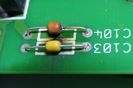
Hi, the capacitor C104 is there only for EMC reasons, doesn't affect the audio signal at all. You may remove it and everything will be OK.Hey Santiago,
I'm new here. I don't speak much English, so I had my question translated by an app. I hope everything was translated correctly.
I own a second-hand JVM410 built in 2012, which has worked perfectly for the last 5 years. One day, it started making a strange noise and smelled burnt. While troubleshooting, I found a burnt capacitor (C104).
Can I repair the amp by replacing the capacitor, or should I be concerned that there are other defects?
Based on the pictures, someone in another forum pointed out that the amp may have been modified. They recommended that I contact you, as there is no one more competent to help me with my problem.
Regards
Chamby
Yes safety standards especially for big companies are very strict. Maybe I will update this circuit with switch so I would use it only when there will be ground loop issues.yes, it is pretty much the same circuit. Some people call it "soft ground" but I am not fan of assigning names to certain circuits.
The no-problem with the circuit is that if for whatever reason the bridge rectifier has a problem it is relatively easy to burn the 10ohm resistor and your ground will be floating. The probablilty of this double fault happening is 0.000000000000000000001% but in the test labs, and following the safety test standards, you may be required to demonstrate that everything is safe when the semiconductors break, regardless of how likely this will happen. The chassis will be still safe but your jacks connectors won't be.
It is a bit the same problem with the external bias points. On their own they are technically not allowed if you want to comply with the required safety standards.
I also think that it is better to sort out the ground loops in a different way, for example with an isolating transformer, than adding these things to the amp. Reason is that you can't assume that ONLY the amp will be grounded like that, you may have effects also grounded like this and then you may be creating a bigger problem than what you started with.
Safety standards are the same for everybody, probably bigger companies take them more seriously as first, you want your products safe to begin with. then the fines can be huge if you are not responsible. For a small company you probably risk bankrupcy if they catch you not complying, you can face legal punishment as well. It is more serious than some people think.Yes safety standards especially for big companies are very strict. Maybe I will update this circuit with switch so I would use it only when there will be ground loop issues.
I thought also about isolating transformers for signals cable but from my experience they cut some highs like using long cables. Also nice trick is to use 10 ohm resistor between ground and send jack ground.
What you have in mind about creating bigger problem when other effect will have this circuit too?