Impedance Measurement with DATS V3 + REW

AlbertA

Roadie
Messages
690
The DATS V3 system is a convenient speaker impedance measurement jig from Dayton Audio.
While Dayton Audio provides software for the jig it unfortunately only runs on Windows.

Thankfully, REW (Room EQ Wizard) includes an impedance measurement tool and provide instructions on how to create your own measurement jig: https://www.roomeqwizard.com/help/help_en-GB/html/impedancemeasurement.html

In order to use a measurement jig with REW, you need to know the value of the sense resistor (Rsense) and have a reference (Rref) resistor for proper calibration.

DATS V3 provides a 1K Ohm calibration/reference resistor, accessible on the outer posts next to the RED and BLACK jacks. However, there was no information on the sense resistor other than some outdated info here.

So I opened up the device to figure it out. I have REV J of the board:
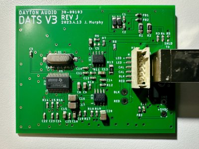
IMG_3927.jpeg

I traced the signals of interest
1752648091979.jpeg


and this is how it works:

The DATS V3 uses a stereo audio codec with integrated USB interface - The TI PCM2900 (IC2). It sends the DAC Left channel output to a headphone 150mW power amplifier - the TI TPA6111A2 (IC1) which drives the connected load.

The output is conditioned via an op-amp provided by the TI LVM358 part (IC3) and fed to the ADC Right Channel input in IC2. This is the "Ref Input" channel that should be used in REW.

The output passes through a 47 Ohm sense resistor (R2) and is conditioned via IC3 and fed to the ADC Left channel input in IC2.

Here's a super high level diagram

DATS_V3_REVJ.png


Now that we know how the jig is set up, we can configure REW (the following is REW running on MacOS):
  • Go to REW->Settings.
  • In Output device, select "USB AUDIO CODEC" - the name advertised by the DATS V3 USB interface
    • Select "L" for the output channel
  • In Input Device, select "USB AUDIO CODEC".
    • Select "L" for the input channel
Screenshot 2025-07-16 at 1.16.58 AM.png

  • Now click the Measure button/icon
Screenshot 2025-07-16 at 1.33.37 AM.png
  • Select "Impedance" for the type
  • Set Ref input to the LINE_IN "R" channel
  • Set -4 dBFS for the level.
  • Set 47 Ohms for Rsense.
  • Go through calibration in the order specified (1. Open circuit cal, 2. Short circuit cal, 3. Reference cal)
    • For reference calibration, enter 1000 ohms and connect the leads to the outer posts of the DATS V3 device.
  • You are now ready to measure the impedance curve of a connected load (Press Start)

Screenshot 2025-07-16 at 1.18.18 AM.png
 
Last edited:
I have a DATS V3. My head hurt trying to figure out how to rig a DIY solution up with my interface. It’s Windows only software like the DATS software that keeps me from fully moving over to a Mac.
 
I'm on the fence about getting one. On one hand, it would be infinitely more portable than my current setup but I'm worried 150mW might be too low to get accurate readings off big speakers.
 
The DATS V3 system is a convenient speaker impedance measurement jig from Dayton Audio.
While Dayton Audio provides software for the jig it unfortunately only runs on Windows.

Thankfully, REW (Room EQ Wizard) includes an impedance measurement tool and provide instructions on how to create your own measurement jig: https://www.roomeqwizard.com/help/help_en-GB/html/impedancemeasurement.html

In order to use a measurement jig with REW, you need to know the value of the sense resistor (Rsense) and have a reference (Rref) resistor for proper calibration.

DATS V3 provides a 1K Ohm calibration/reference resistor, accessible on the outer posts next to the RED and BLACK jacks. However, there was no information on the sense resistor other than some outdated info here.

So I opened up the device to figure it out. I have REV J of the board:

View attachment 48749

I traced the signals of interest
View attachment 48756

and this is how it works:

The DATS V3 uses a stereo audio codec with integrated USB interface - The TI PCM2900 (IC2). It sends the DAC Left channel output to a headphone 150mW power amplifier - the TI TPA6111A2 (IC1) which drives the connected load.

The output is conditioned via an op-amp provided by the TI LVM358 part (IC3) and fed to the ADC Right Channel input in IC2. This is the "Ref Input" channel that should be used in REW.

The output passes through a 47 Ohm sense resistor (R2) and is conditioned via IC3 and fed to the ADC Left channel input in IC2.

Here's a super high level diagram

View attachment 48757


Now that we know how the jig is set up, we can configure REW (the following is REW running on MacOS):
  • Go to REW->Settings.
  • In Output device, select "USB AUDIO CODEC" - the name advertised by the DATS V3 USB interface
    • Select "L" for the output channel
  • In Input Device, select "USB AUDIO CODEC".
    • Select "L" for the input channel
View attachment 48753
  • Now click the Measure button/icon
View attachment 48755
  • Select "Impedance" for the type
  • Set Ref input to the LINE_IN "R" channel
  • Set -4 dBFS for the level.
  • Set 47 Ohms for Rsense.
  • Go through calibration in the order specified (1. Open circuit cal, 2. Short circuit cal, 3. Reference cal)
    • For reference calibration, enter 1000 ohms and connect the leads to the outer posts of the DATS V3 device.
  • You are now ready to measure the impedance curve of a connected load (Press Start)

View attachment 48754
Hi,
Can you measure and post the value of capacitor and resistor 22D, 80C. Similarly signal path.
Thanks in advance
 
@raghav, Which designators are you referring to? C9, R10 for example?
Thanks for Signal trace and info provided is useful.

If you could give values of C1, C2, C8, C9, C12, C13, C14,C16, C17, C18,C19, C20 which are in signal path
I remember reading in some other forum that they used custom value for resistors. So wanted to confirm on values of 22D , 80C .
Also picture of other side of PCB will help.

i followed above link. Has interesting information.

I have Behringturd U-Control Uca202 Usb Audio Interface which has same PCM2900C(Clone) chip , It detects by DatsV2, Dats V3 and REW software, i want to use as Dats V3 system by adding simple addon circuit to UCA202 built using LMV358, TPA6111A2.

If time permits I like to design PCB as well.

Your help is much required and appreciated.
 
Last edited:
@raghav those are SMD resistor codes. 22D should be a 165k resistor. 80C should be 66.5k.

@AlbertA your posts for the DATS has inspired me to play with mine a lot more lately.
Yes by SMD code what value you specified is correct, but i remember reading in some other forum that they used custom value. So wanted to confirm. if @AlbertA could read value of 22D , 80C and confirm will help.
 
Just buy one and measure what you want to measure.
Not available locally, in my country To buy from europe or US shipping costs 3 times of item. So want understand and build better version using free software like REW. It is used for hobby not for commercial.

From China similar item not available.
 
Last edited:
Not available locally, in my country To buy from europe or US shipping costs 3 times of item. So want understand and build better version using free software like REW. It is used for hobby not for commercial.

From China similar item not available.

If you want to build your own, you don't need to and don't want to start with the DATS. Google is your friend on how to put together your own measuring system which can be done cheaper and better than the DATS if you aren't going to be using their software.

For example:

 
Ok thank you, Please help to get values of C1, C2, C8, C9, C12, C13, C14,C16, C17, C18,C19, C20 and 22D , 80C
R1 47.6
R2 47.1
R3 159k
R4 158.7k
R6 66.1k
R7 66.1k
R9 .91M
R10 65.4k
R11 160.2k
R12 65.7k
R13 1k
R14 1.49k
R15 33k
R16 33k
R17 65.3k

C8 6.7uF
C9 6.8uF
C13 2.7uF
C16 60uF
C17 58uF
C18 6.5uF
C20 60uF

These are the only ones I could get a good reading in-circuit.
 
R1 47.6
R2 47.1
R3 159k
R4 158.7k
R6 66.1k
R7 66.1k
R9 .91M
R10 65.4k
R11 160.2k
R12 65.7k
R13 1k
R14 1.49k
R15 33k
R16 33k
R17 65.3k

C8 6.7uF
C9 6.8uF
C13 2.7uF
C16 60uF
C17 58uF
C18 6.5uF
C20 60uF

These are the only ones I could get a good reading in-circuit.
Thank you, This gives idea. C14 or C19 and C12 was very important.
One more request, can you give photo of other side of PCB.
 
Last edited:
Back
Top